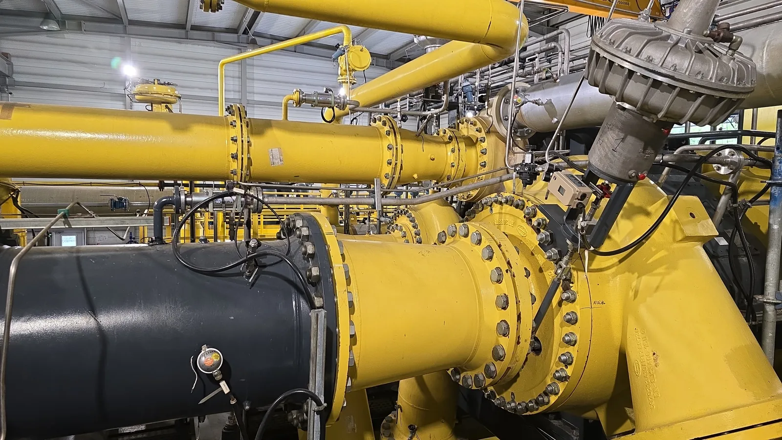
Steam Turbine Overhaul Case Study: MAN Turbo MARC 4 Casing Recovery After a Five Week Outage
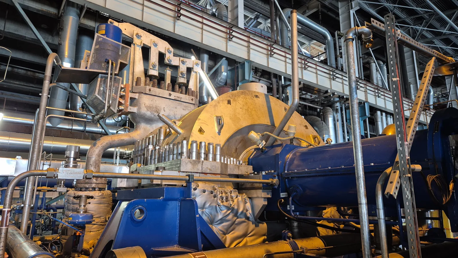
A Planned Overhaul That Became a Turbine Recovery
Scope, Preparation and First Findings
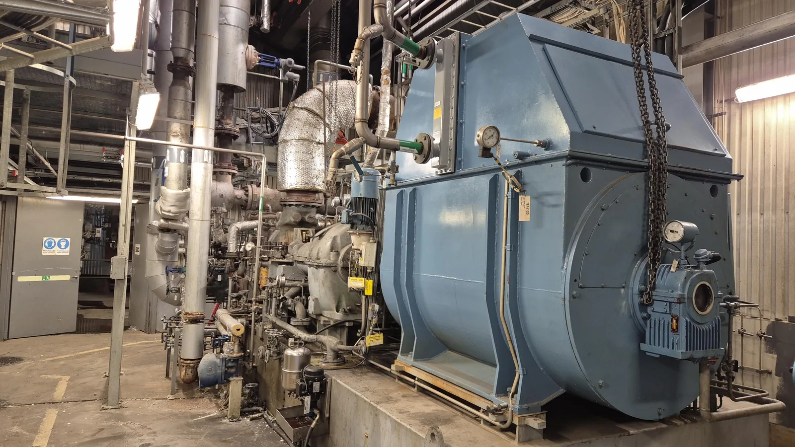
When Energetic Machinery secured a major overhaul on a MAN Turbo MARC 4 H02 condensing steam turbine, the assignment was planned around a demanding five week outage. The plant operator had purchased a substantial stock of spare parts, while the engineering team in Belgium prepared the schedule, technical documentation, tooling plan and inspection programme.
The original scope covered complete disassembly, cleaning and inspection of the turbine, together with work on the rotor, gearbox, generator, valves, bearings, seals and oil systems. No major equipment problems had been reported at the tender stage.
Once the turbine was opened, the situation changed. The findings included:
-
Extensive erosion on casing split lines and carrier seats
-
Poor contact across large parts of the horizontal split line
-
Damaged seals and traces of earlier repairs
-
Additional parts that had to be repaired, replaced or manufactured
What began as a tightly planned overhaul developed into a coordinated turbine recovery involving site inspection, engineering, photogrammetry, three dimensional scanning, welding, mobile machining, laser cladding and rapid component manufacturing.
Inspection Before Defining the Repair
What Marking Blue Could and Could Not Show
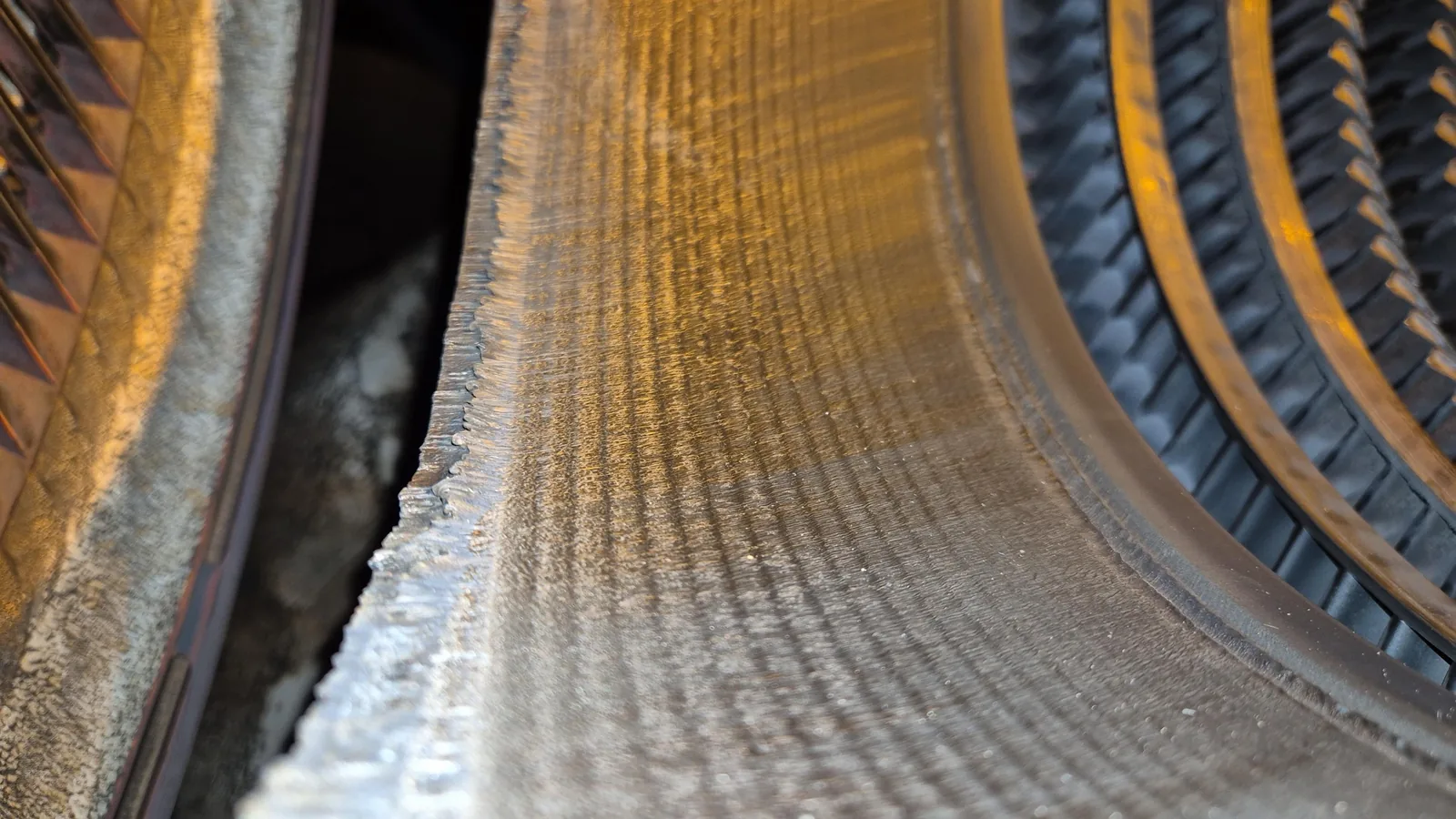
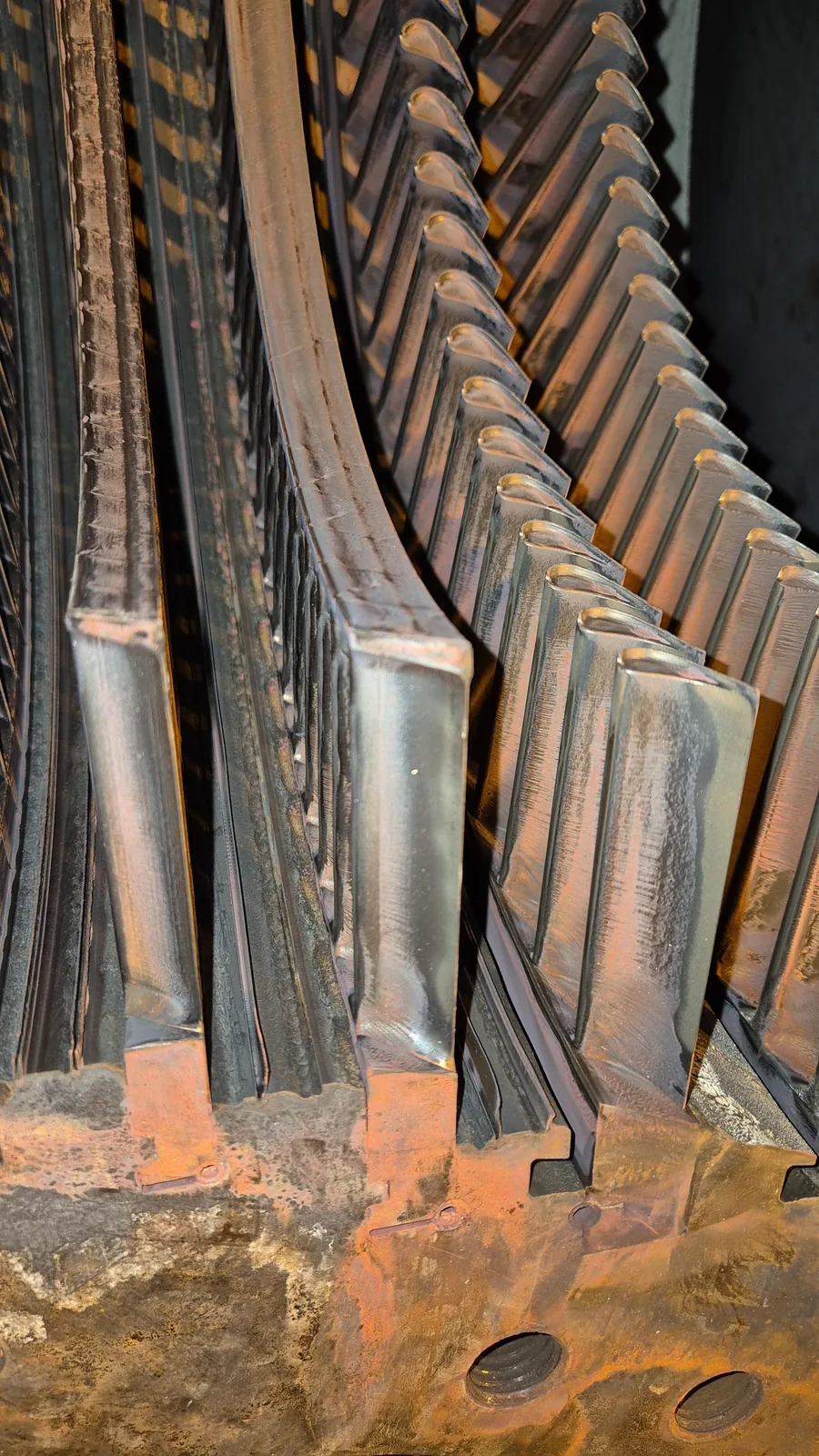
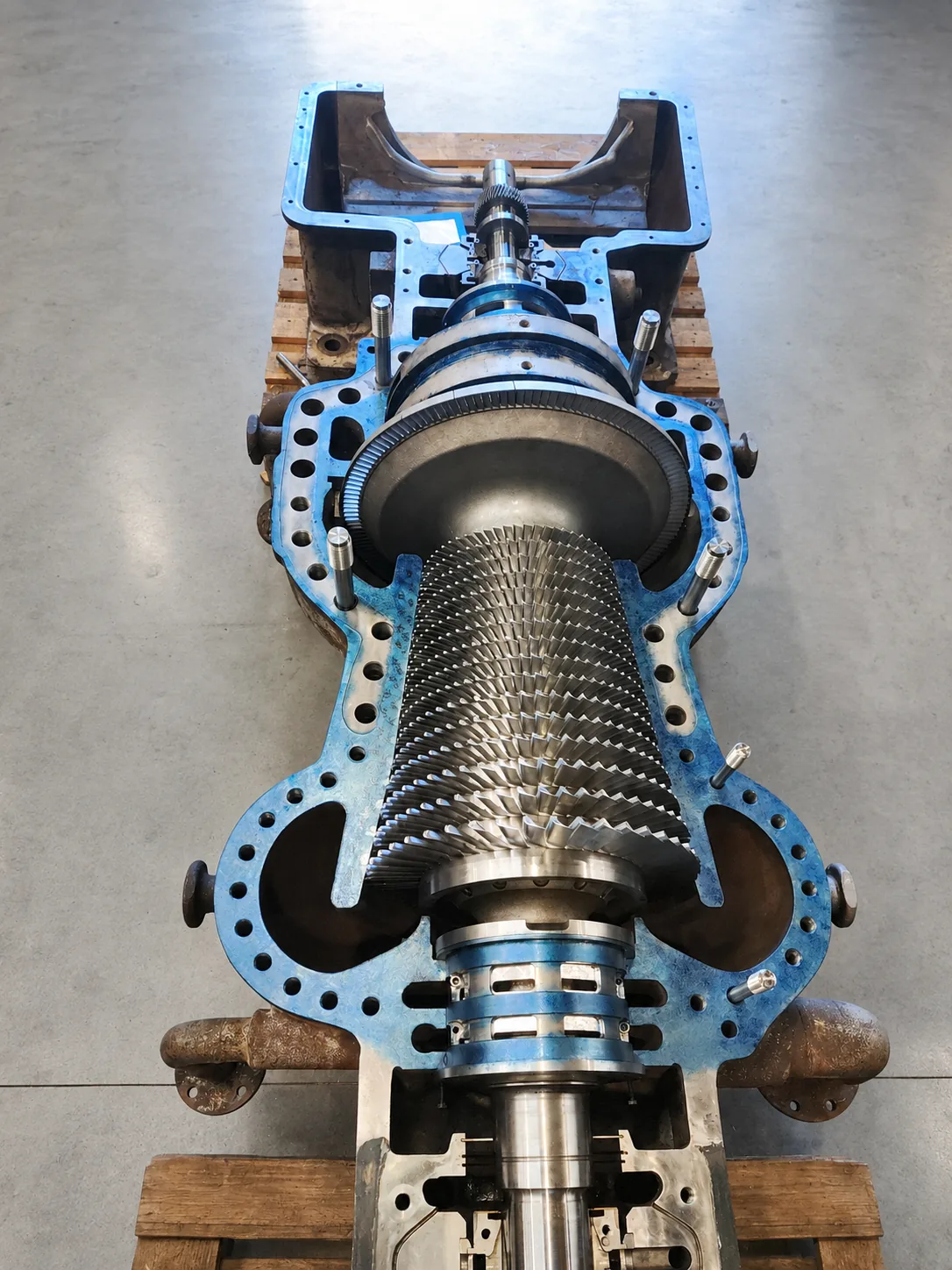
The upper and lower casings, carrier seats, blade carriers, seals, bearings and associated components were cleaned and inspected. Contact between mating surfaces was checked using marking blue, while erosion, earlier repairs and local defects were documented.
The lower casing showed erosion at several carrier seats and poor contact across large parts of the horizontal split line. The problem extended through several turbine stages, the outlet area and both ends of the casing.
The upper casing showed a similar pattern. Carrier seats three, four and five had erosion at the split line and damage on their axial seating surfaces. Poor contact was also identified at the non drive end and through the middle section, with a possible leakage path towards the split line bolt holes. Damaged brush seals and a cracked nozzle weld added to the scope.
These findings showed where sealing and fit had deteriorated, but visual inspection could not reveal how the complete upper and lower casing surfaces would interact after assembly. Opposing deviations can partly compensate for each other or combine into a larger gap, so repairing only the visible erosion could leave leakage paths in place.
Energetic Machinery therefore continued in controlled stages. Findings were documented, repair alternatives were evaluated and acceptance criteria were defined before the wider scope was released. Each decision could then be based on measured condition rather than assumption.
Measuring the Full Casing Condition
Photogrammetry and Three Dimensional Scanning
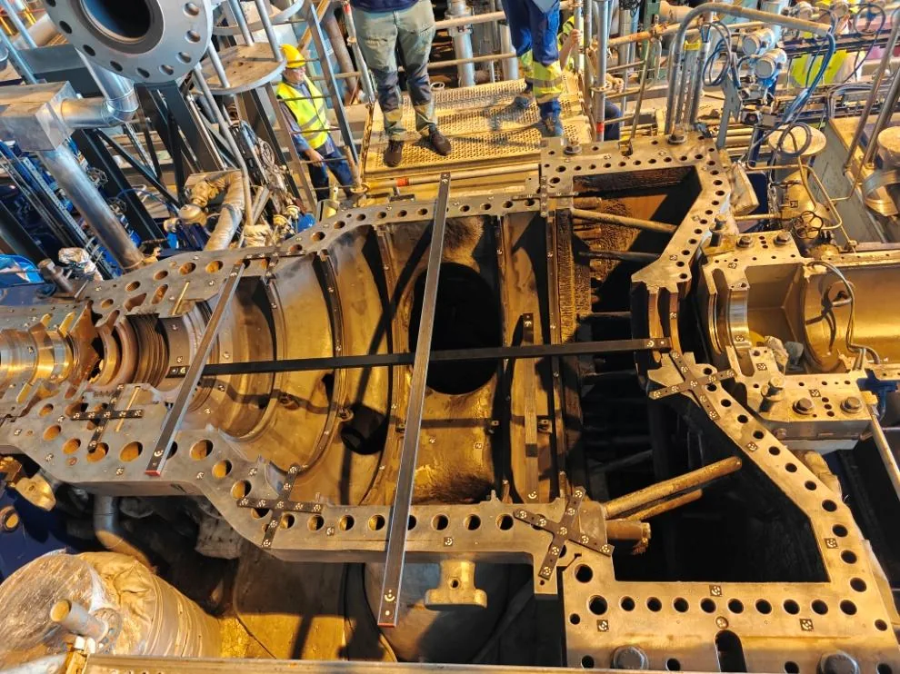
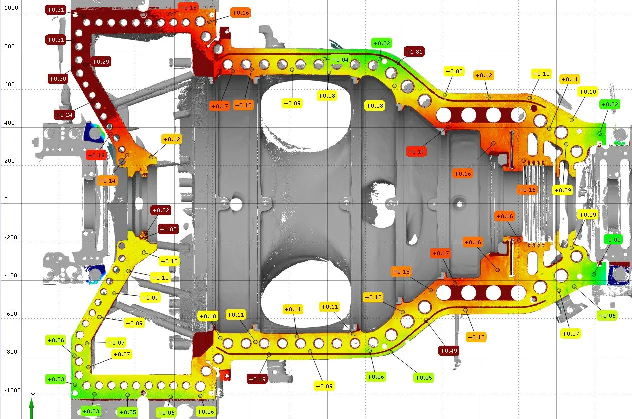
Photogrammetry and three dimensional scanning were used to create a digital model of both casing halves. Reference markers and calibrated scale bars were positioned before the accessible split line and internal areas were scanned.
The digital meshes allowed the engineering team to assess each casing separately and then combine the surfaces to calculate their expected relationship once assembled.
The results confirmed inadequate contact across most of the split line. Clearance was most severe around the Curtis wheel and first stage, the final two stages and the exhaust section. The exhaust area of the lower casing also appeared distorted. When the deviations of both halves were combined, the calculated clearance reached approximately 0.3 mm in several areas.
The measurements matched the physical evidence. Black steam markings extended towards the bolt holes, showing that steam had reached areas outside the intended sealing boundary and indicating a risk of leakage through the holes if left untreated.
The scan also prevented an unsuitable shortcut. Simply removing material until both surfaces appeared flat would not restore the correct relationship between the casing halves. Damaged areas first had to be rebuilt, followed by controlled machining and verification.
Lower Casing Split Line, Repaired On Site
Grinding, TIG Welding and Mobile Machining
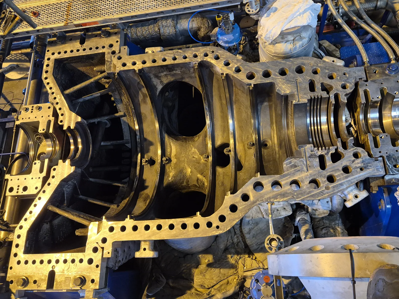
The lower casing remained in the plant, so the repair had to be completed on site. Contaminated and eroded material was removed by controlled grinding before the affected areas were rebuilt by TIG welding.
Careful heat control was essential, since uneven heating or cooling could introduce further distortion. Holes and complex features also had to be protected, and the completed welds required non destructive inspection.
A mobile milling machine then restored the complete split line. Measurements and final adjustments continued until the specified flatness was achieved and local deformation had been corrected.
This type of repair may be relevant when contact checks show large unmarked areas, steam staining reaches the fasteners, or local erosion has developed into a wider sealing problem. Local scraping cannot correct a surface that no longer shares a reliable reference.
Upper Casing Split Line: Restoration by Laser Cladding
Adding Material Instead of Removing It
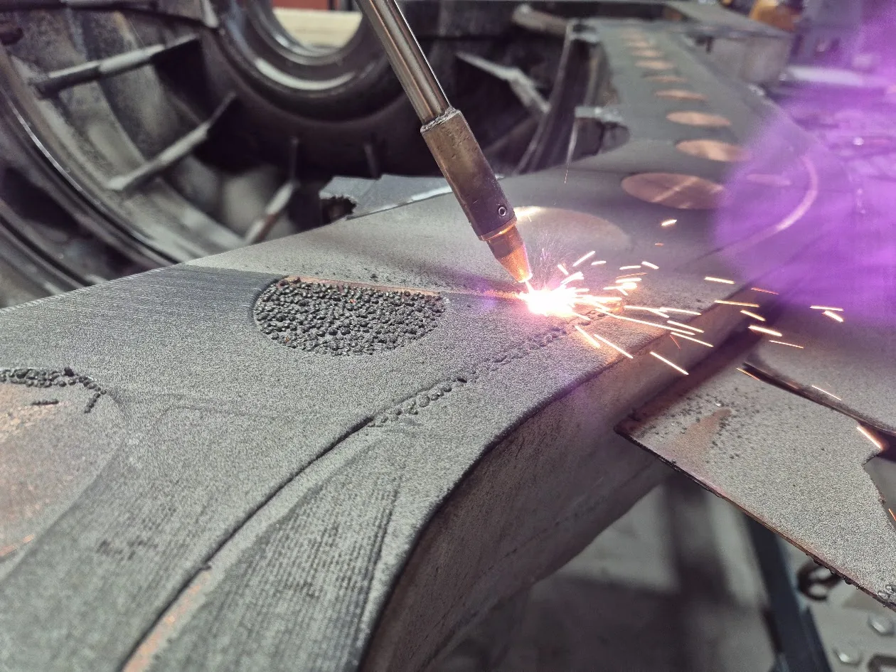
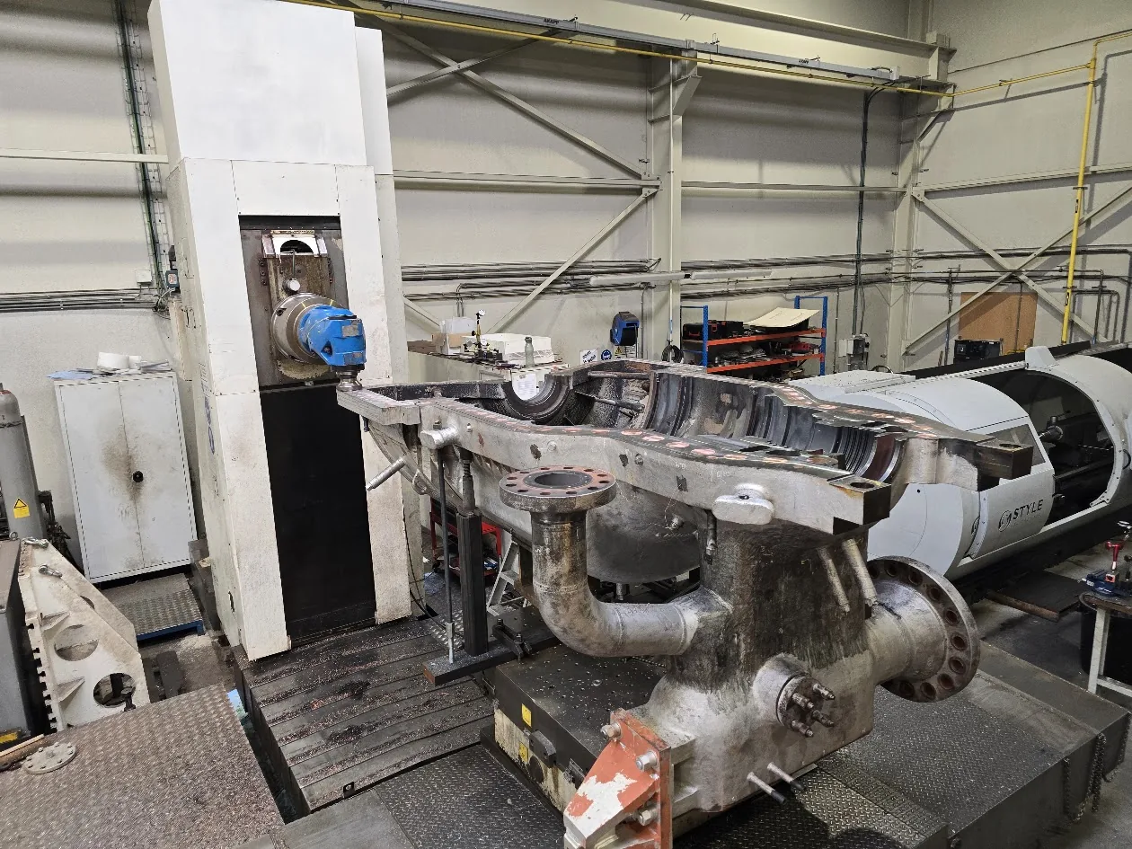
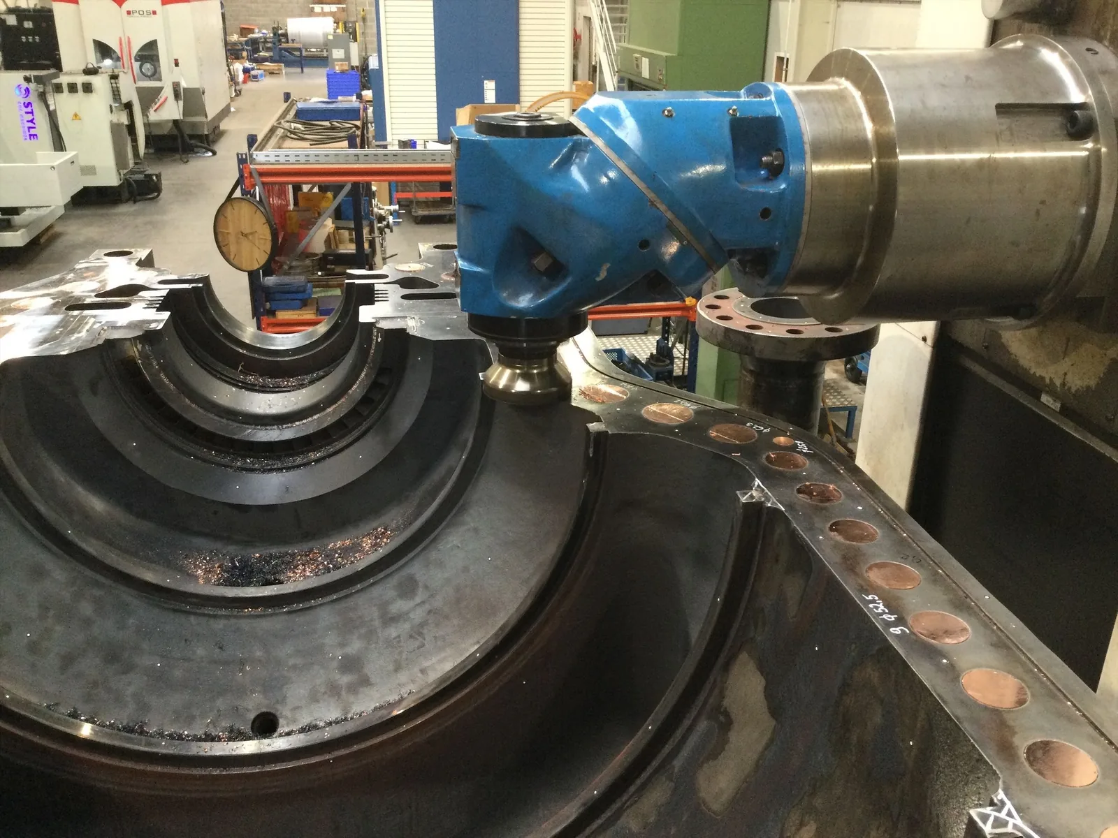
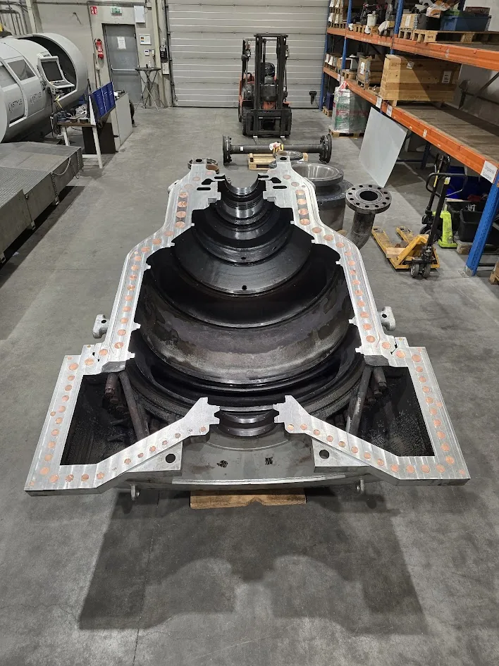
With the casing condition measured and the repair scope defined, the upper casing split line could be restored in the workshop.
The surface was prepared and reference points established. Copper plugs protected holes and other geometric features before the complete flange surface was rebuilt by laser cladding.
After cladding, the split line was machined to the required geometry and checked against the specified flatness tolerance. Controlled material addition followed by precision machining restored the surface without removing more material from an already damaged casing.
Laser cladding can be suitable when erosion extends across a large sealing surface, or when earlier local repairs no longer provide sufficient contact. Accurate machining and measurement remain essential to create the final interface.
Carrier Seats and Blade Carriers
Restoring the Internal Geometry
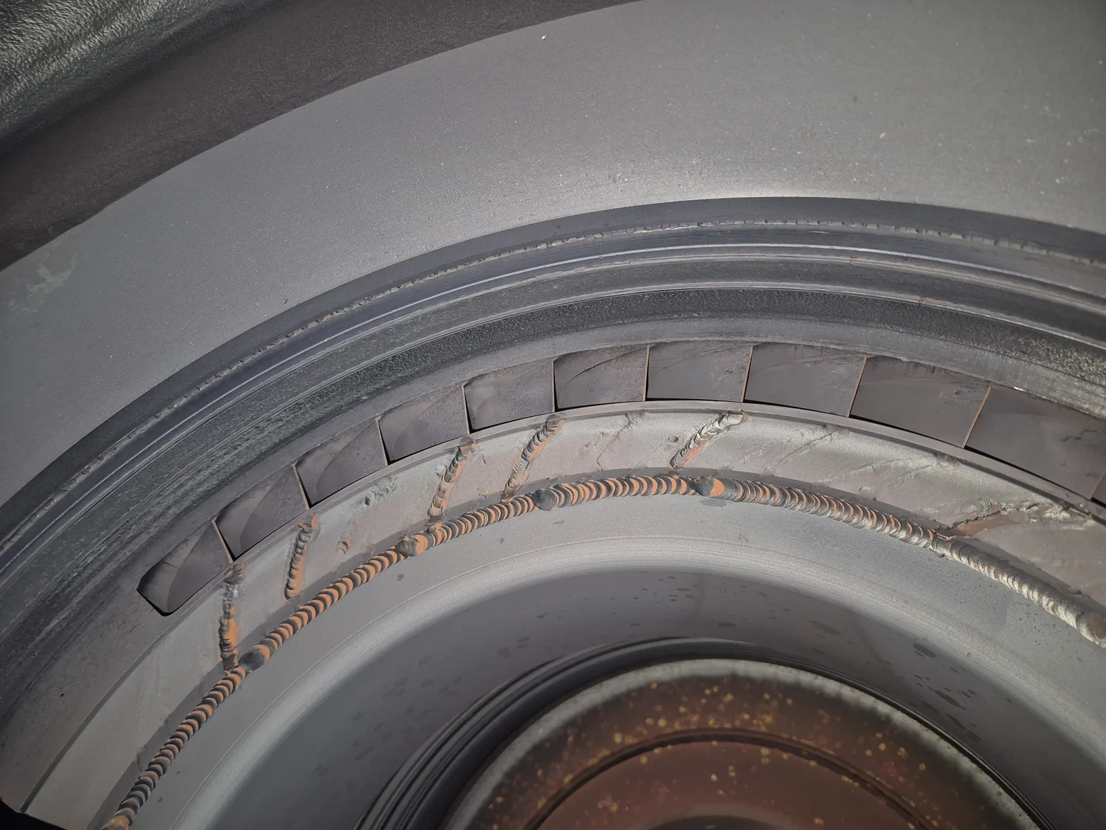
The carrier seats in both casing halves had local erosion close to the split line and on the axial contact surfaces. These areas locate the blade carriers and help maintain the internal turbine geometry.
The repair included grinding away damaged material, rebuilding the areas by TIG welding, machining where required and manual finishing to restore the fit. Acceptance focused on visual quality and on whether each carrier seated correctly in the casing.
Carrier seat repairs may be required when erosion is visible at the edges, marking blue shows incomplete contact, or a carrier no longer fits consistently. Correcting the split line alone can leave the internal components poorly supported.
Blade Carrier Refurbishment
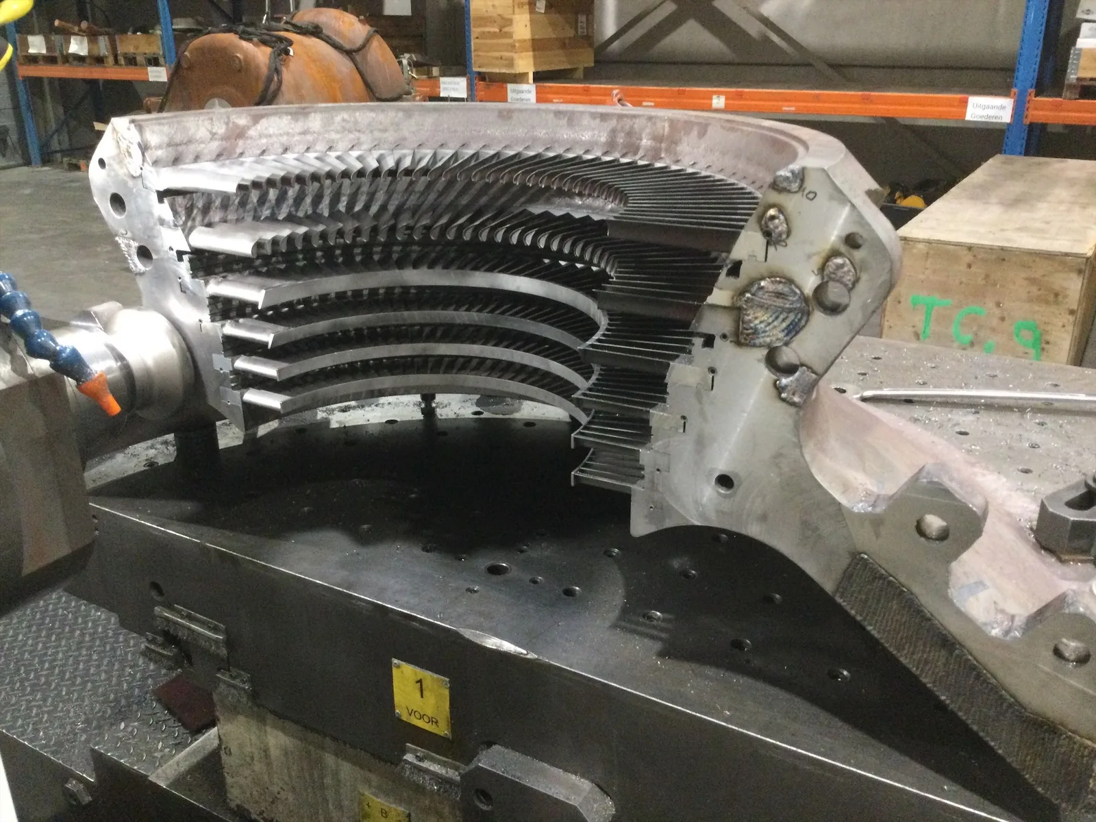
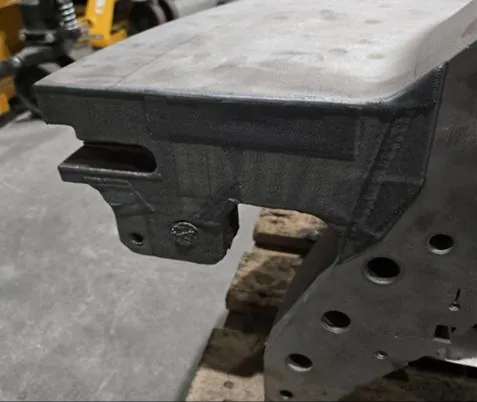
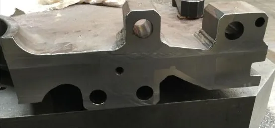
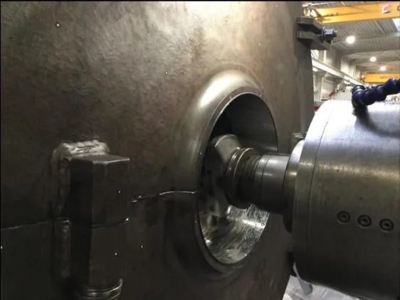
The five blade carriers required different levels of repair. Carrier one received a new final row sealing strip and split line polishing. Damaged sealing strips on carrier two were straightened, followed by split line polishing.
Carriers three, four and five required more extensive work. Their split lines were prepared, rebuilt by laser cladding, machined and polished, again with copper plugs protecting holes and features. Earlier repairs and bolt flanges on carrier three were reworked and new locating blocks were manufactured. Carrier four also required laser cladding and machining of its radial sealing surface. New locating blocks were produced for all three carriers.
The repair records show optimal contact on carriers three and five, and good contact on carrier four after the work.
Where Repair Was Deliberately Not Carried Out
Not every visible area was repaired. Some erosion between the static blades could not be reached without removing the blades, which would probably have required destructive removal. New sealing strips in severely eroded grooves also created a risk of detachment during operation.
The lowest risk decision was to leave those specific areas untreated and to document the remaining condition. Recording what was deliberately not repaired, and why, is part of an honest handover.
Manufacturing Components That Were Not Available
From Measurement to Installed Part
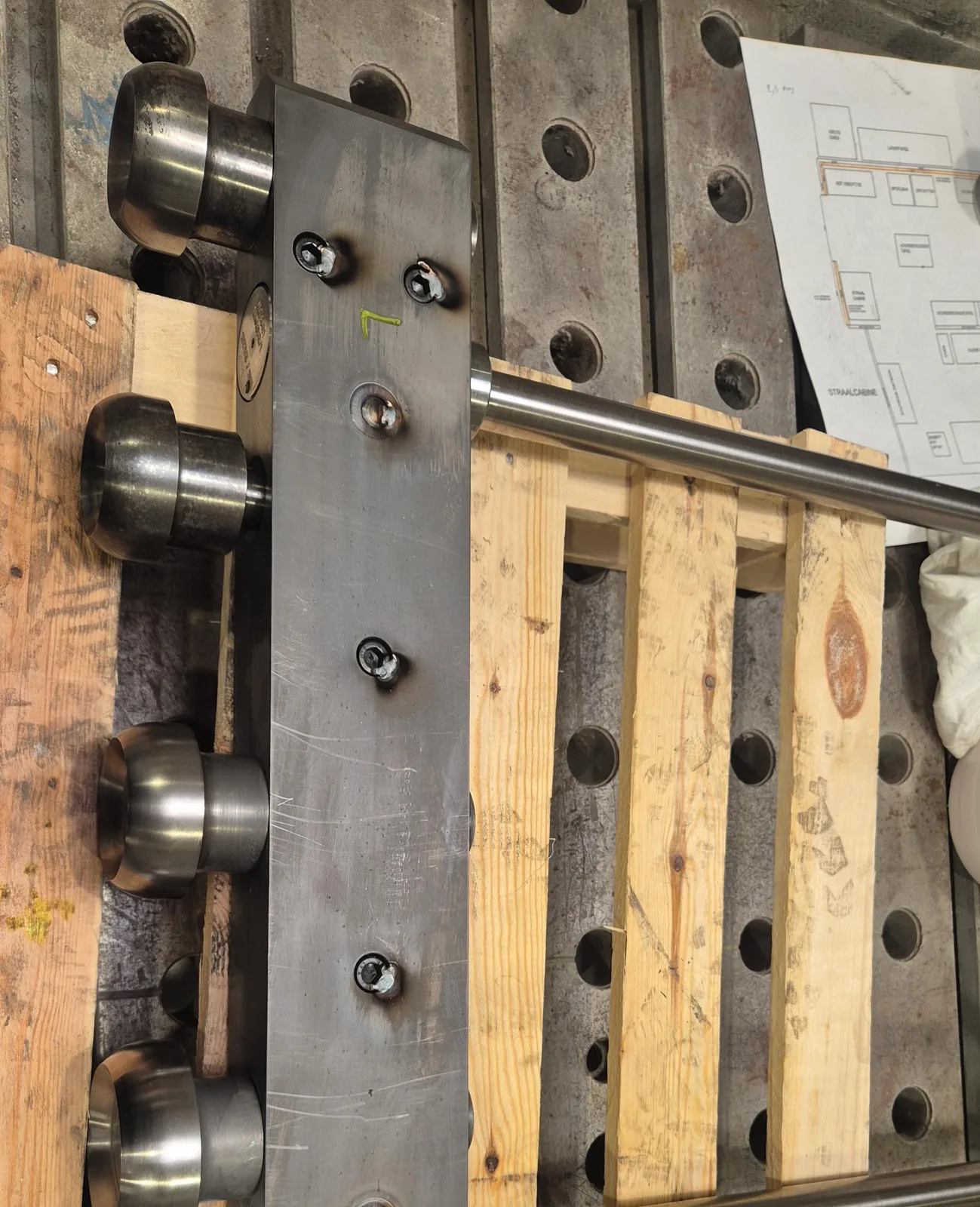
The spare parts preparation made a major difference, but it could not cover every finding.
-
Two regulation valve stems were unavailable and were manufactured in house
-
Two damaged M60 split line bolt assemblies required new studs, cap nuts and expansion sleeves
-
All turbine bearings were replaced, but six pads for the non active side of the axial bearing were not available from stock and a new set was manufactured
-
The generator oil seals were replaced and the nozzle weld was repaired
This capability matters when an overhaul reveals uncommon parts that are no longer readily available. The team can move from measurement and engineering to machining and installation without waiting for a standard supply chain solution.
Verification Before Reassembly
Returning Every Repair to the Same References
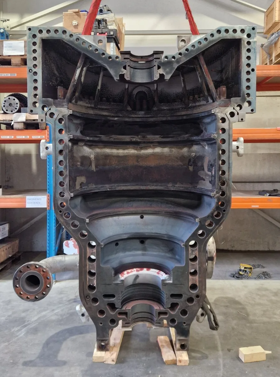
Every repair required defined acceptance criteria before the machine could move towards reassembly. The casing split lines required documented flatness measurements and visual inspection. Welded areas required non destructive testing. Carrier seats had to show correct fit. Blade carrier split lines were checked with marking blue, while repaired sealing surfaces and manufactured components had to meet their dimensional requirements.
This stage is essential when several repair methods and locations are involved. On site welding, mobile machining, laser cladding and component manufacturing must all return to the same mechanical references and work together in the final assembly.
Results: Successful Start Up and Stable Operation
What the Operator Received
After reassembly the turbine was started up on 31 October 2025, following a coordination meeting on the start up procedure and a controlled overnight heat up of the inlet pipework.
The outcome:
-
The machine reached full speed, was synchronised and ran stable, and was still stable at the follow up check the next day.
-
Vibration analysis showed only a residual unbalance at one times running speed. The spectrum showed no other issues.
-
The orbit showed no indication of rubbing, and the shaft centreline followed the normal pattern for a tilting pad bearing.
-
Casing split lines, carrier seats, blade carriers and manufactured components were handed over with documented measurements, non destructive testing results and inspection records.
-
The remaining unrepaired erosion between the static blades was documented with the reasoning behind that decision.
A controlled heat up matters on a condensing turbine of this type. Wet steam and unstable gland steam pressure can cool the gland seal carrier while the rotor is already expanding, which reduces clearance and can cause the seals to rub. Time spent on heating and on stable gland steam conditions before increasing speed is time well spent.
One Coordinated Recovery
Why the Original Schedule Is Not the Only Measure
The project developed far beyond the original five week assumption, but the preparation completed before the outage created room to respond.
The plant operator had spare parts, site resources and local welding capability available. Energetic Machinery connected the field team on site with engineering and workshop specialists in Belgium. Three dimensional measurement, mobile machining, laser cladding and rapid manufacturing were integrated into one technical plan.
For the operator, this created a clear route from unexpected findings to measured condition, defined repair methods and documented acceptance criteria.
The project showed that the value of an overhaul partner is not limited to following the original schedule. It is also the ability to recognise when the machine requires a different plan, and to organise the technical resources needed to manage that change.
FAQ: Steam Turbine Casing Repair
Why measure a casing split line in three dimensions instead of using marking blue alone?
Marking blue shows where two surfaces touch, but not how the complete halves will interact once bolted together. Deviations on the two halves can cancel out or add up. On this turbine the combined clearance reached about 0.3 mm in several areas, which marking blue alone would not have quantified.
What does steam staining near the split line bolt holes indicate?
It shows that steam has reached areas outside the intended sealing boundary. If that is left untreated, there is a risk of leakage through the bolt holes themselves, not only along the flange face.
Can a casing split line be machined flat again without welding first?
Not when material has been lost to erosion. Removing material until both surfaces look flat does not restore the correct relationship between the halves, and it takes thickness out of a casing that is already damaged. The eroded areas are rebuilt first, by TIG welding or laser cladding, then machined and verified.
When is laser cladding the right choice on a sealing surface?
When erosion extends across a large area, or when earlier local repairs no longer give sufficient contact. It adds controlled material to the surface so the final geometry can be machined rather than ground away.
What happens when an overhaul reveals a part that is not available?
It can be measured and manufactured. In this project two regulation valve stems, split line bolt assemblies and a set of six axial bearing pads were produced rather than waited for.
Is it acceptable to leave some damage unrepaired?
Yes, when repairing it would create a larger risk than leaving it. Here, fitting new sealing strips into severely eroded grooves risked detachment in operation, and reaching erosion between the static blades would probably have required destructive removal of the blades. That condition was documented instead.
Conclusion: The Most Visible Damage May Be Only Part of the Problem
This type of investigation may be relevant if a turbine shows steam staining along the split line, erosion around carrier seats, recurring sealing problems, damaged labyrinths, poor marking blue contact or visible distortion after opening.
The key lesson is simple. A planned overhaul can reveal a condition that was impossible to confirm before disassembly, and the most visible damage may represent only part of the problem.
Energetic Machinery combines structured inspection with field service, engineering, three dimensional measurement, workshop repair, laser cladding, mobile machining and component manufacturing. This allows the repair scope to be based on the actual mechanical condition of the turbine rather than on the original assumption.