Steam Turbine Case Study: From a Sudden Blade Failure to a Completely Rebladed Brown Boveri DGSS
A Machine That Failed Between Two Start Attempts
What the Operator Saw
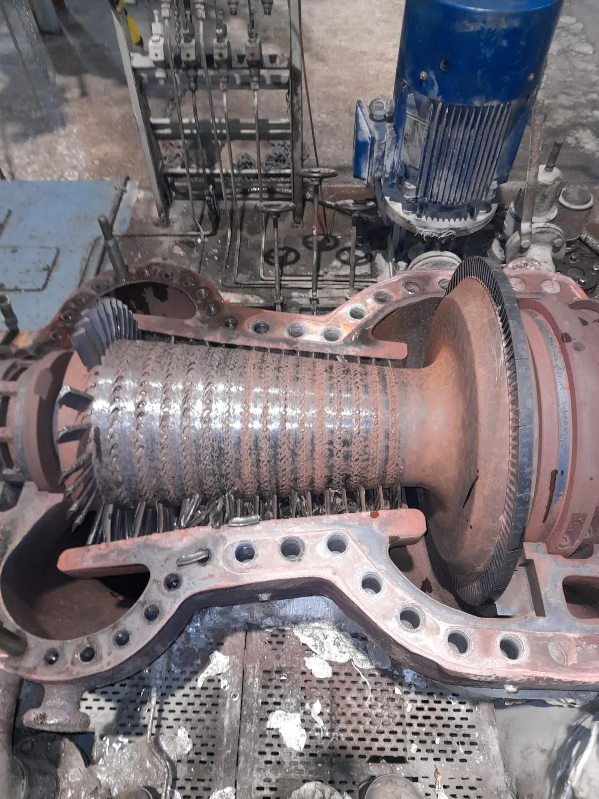
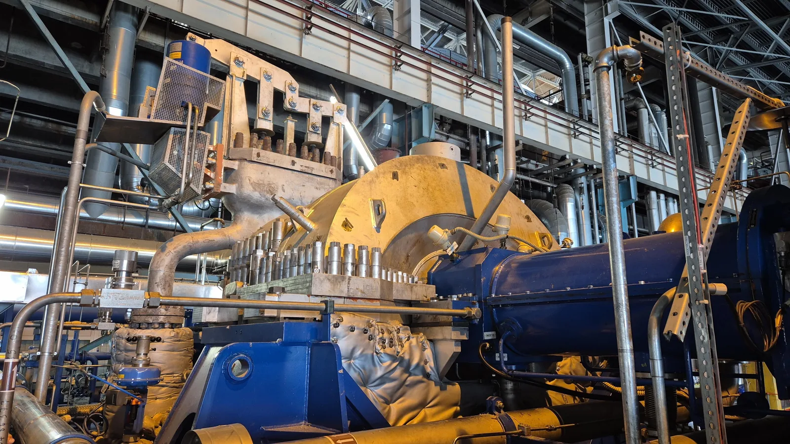
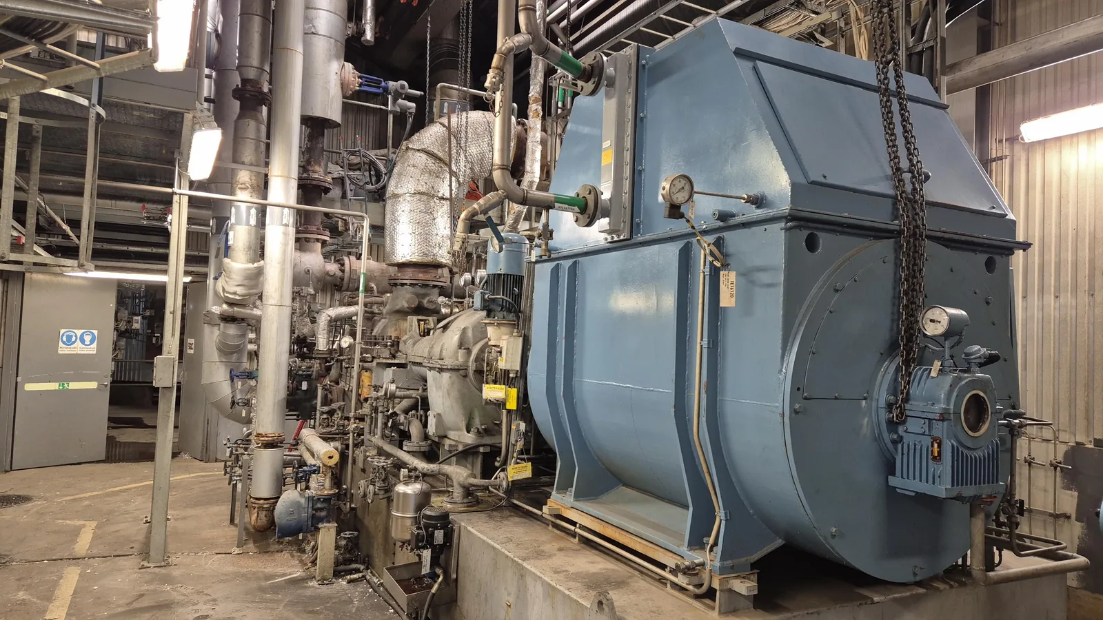
The machine is a Brown Boveri DGSS steam turbine driving a generator through a gearbox. It had run without complaint until the day it was stopped for a reason that had nothing to do with the turbine itself.
The generator temperature was rising because its cooling air inlet was obstructed. When the reading approached the high temperature alarm that trips the train, the operator stopped the machine deliberately. Expecting an outage of two to three hours, the turbine was cooled down.
Once the air inlet was cleared and the generator had come back down in temperature, the turbine was restarted. At approximately 1.6 MW a strong metallic noise appeared. The machine was stopped immediately. The decision was taken to open the machine.
Why the Operator Asked Several Parties
The operator approached Energetic Machinery, several other service providers and the original equipment manufacturer with the same question, and compared the answers on three points: the technical solution, the cost, and the lead time to get the machine back in service.
A quotation for a machine in this condition is only as good as the diagnosis behind it. Energetic Machinery started by reconstructing the sequence of events and working out what could physically have caused the damage, before writing a scope. The scope followed from the failure mechanism, not the other way around.
Root Cause Analysis Before Any Repair Scope
The Evidence Inside the Machine
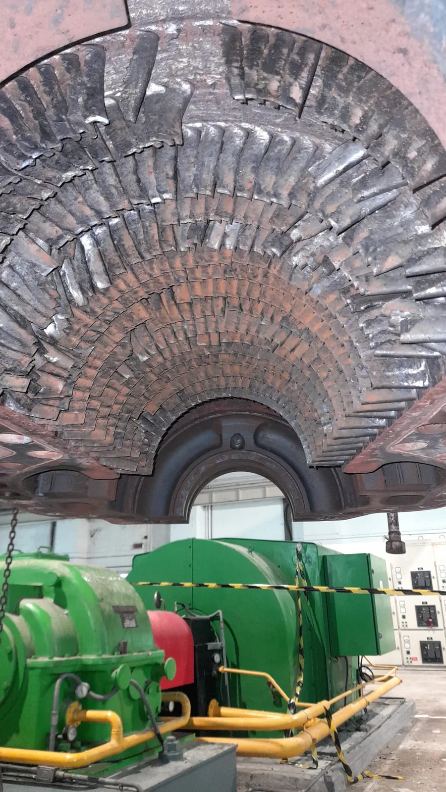
Opening the turbine showed severe and widespread damage to the rotor blading, with clear evidence of contact between rotating and stationary parts. Almost every rotor blade had sheared off. The stator blades showed consequential damage only, which is itself a diagnostic fact rather than a detail.
Inspection records from earlier overhauls gave a nominal blade tip clearance of about 0.5 mm. For contact of this kind to occur across the whole rotor, that clearance must have been reduced to essentially zero.
A Mechanism, Not a Culprit
The available data showed a machine that had functioned properly right up to the restart. The noise and the damage therefore happened at the same moment. The most consistent explanation is that water gathered in the machine during the standstill and entered the steam path at the restart.
The thermal behaviour explains the rest. Rotor and casing are each fixed at one point and grow away from it. On a normal start the rotor heats up and expands faster than the casing, so tip clearance temporarily increases before the casing catches up. Water entering a rotor that is being warmed up reverses that: the rotor cools and contracts faster than the casing around it, the clearance closes from both sides at once, and every rotor blade touches at more or less the same instant.
That mechanism also explains why the stator suffered so much less. The rotating blades were the ones being driven into stationary metal.
A rub caused by a single mechanical defect is a local repair. A rub caused by a thermal event is a full steam path job, because every blade in the machine saw the same event. Establishing which of the two applied here is what decided the scope.
Rotor and Stator Recovery
Removing Blades That Would Not Come Out
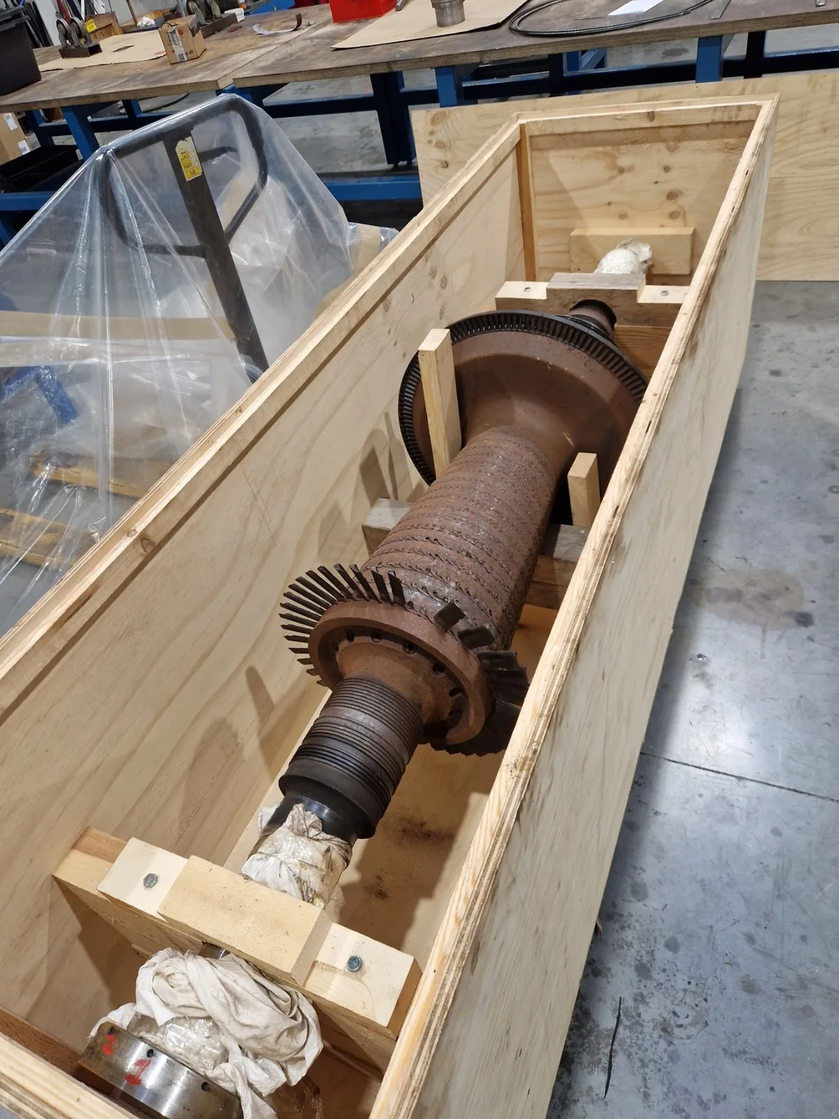
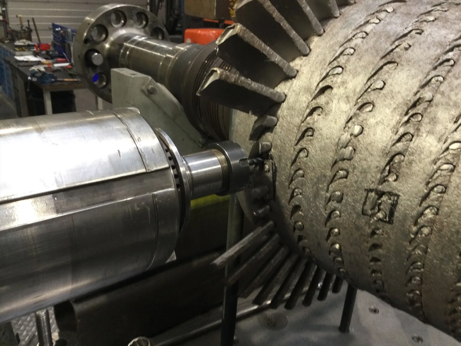
The damage to the rotor left no usable blade to serve as a reference sample. Energetic Machinery therefore carried out the engineering of both rotor and stator blading, including the Curtis stage, from the machine itself and from the available documentation.
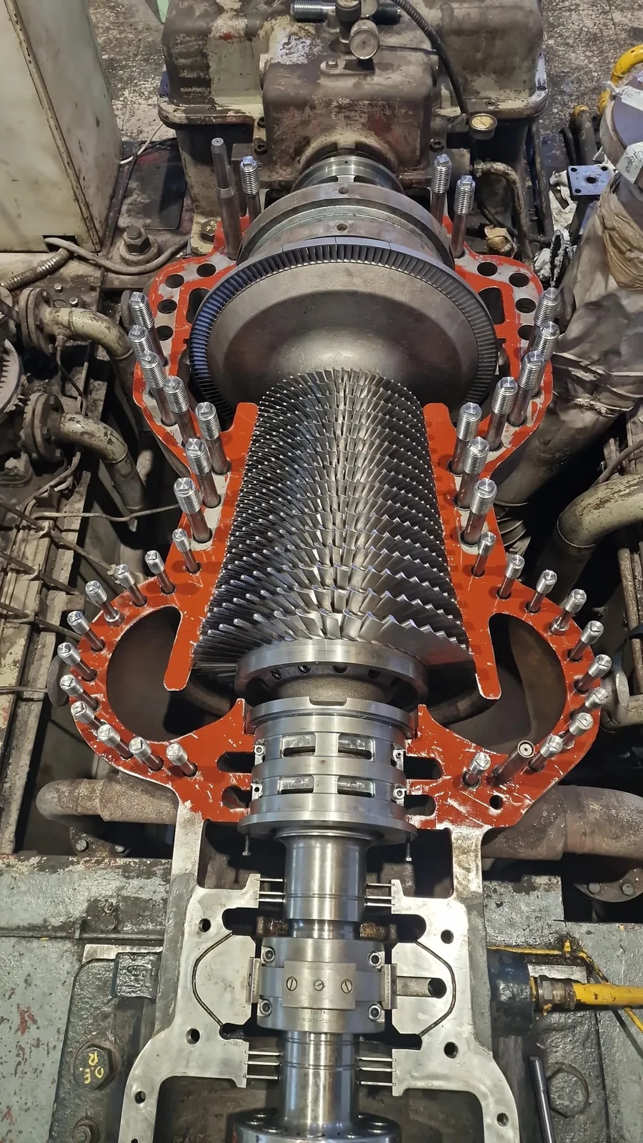
Removing the damaged blading was the slowest part of the work. Some blades had effectively seized in their roots and each one had to be taken out individually by drilling and machining, without damaging the groove that would carry the new blade. The stator blades were removed as well, so that every affected area could be inspected rather than assumed.
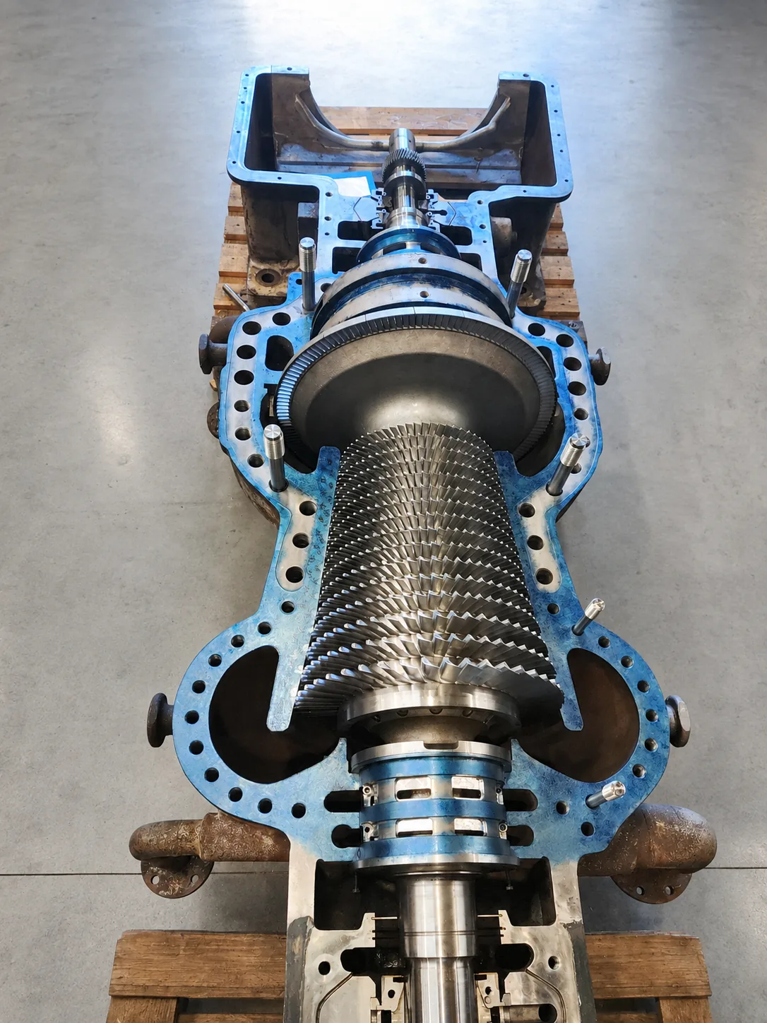
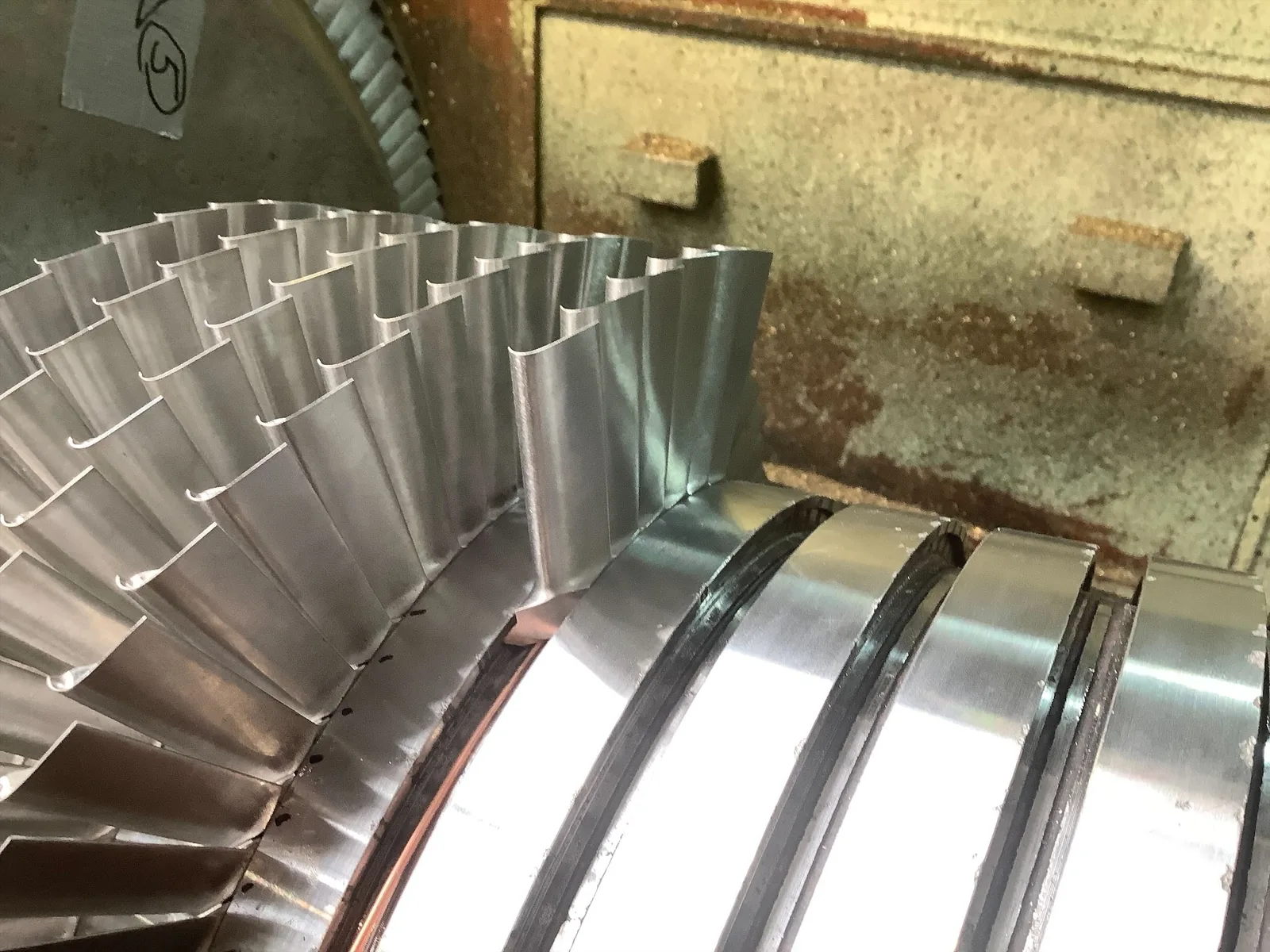
The scale is worth stating plainly. The rotor carries 1,001 blades across sixteen rows, and the stator carries a comparable number in the same sixteen rows. Every one of them came out, and every one of them was replaced.
Cleaning, Testing and Measuring
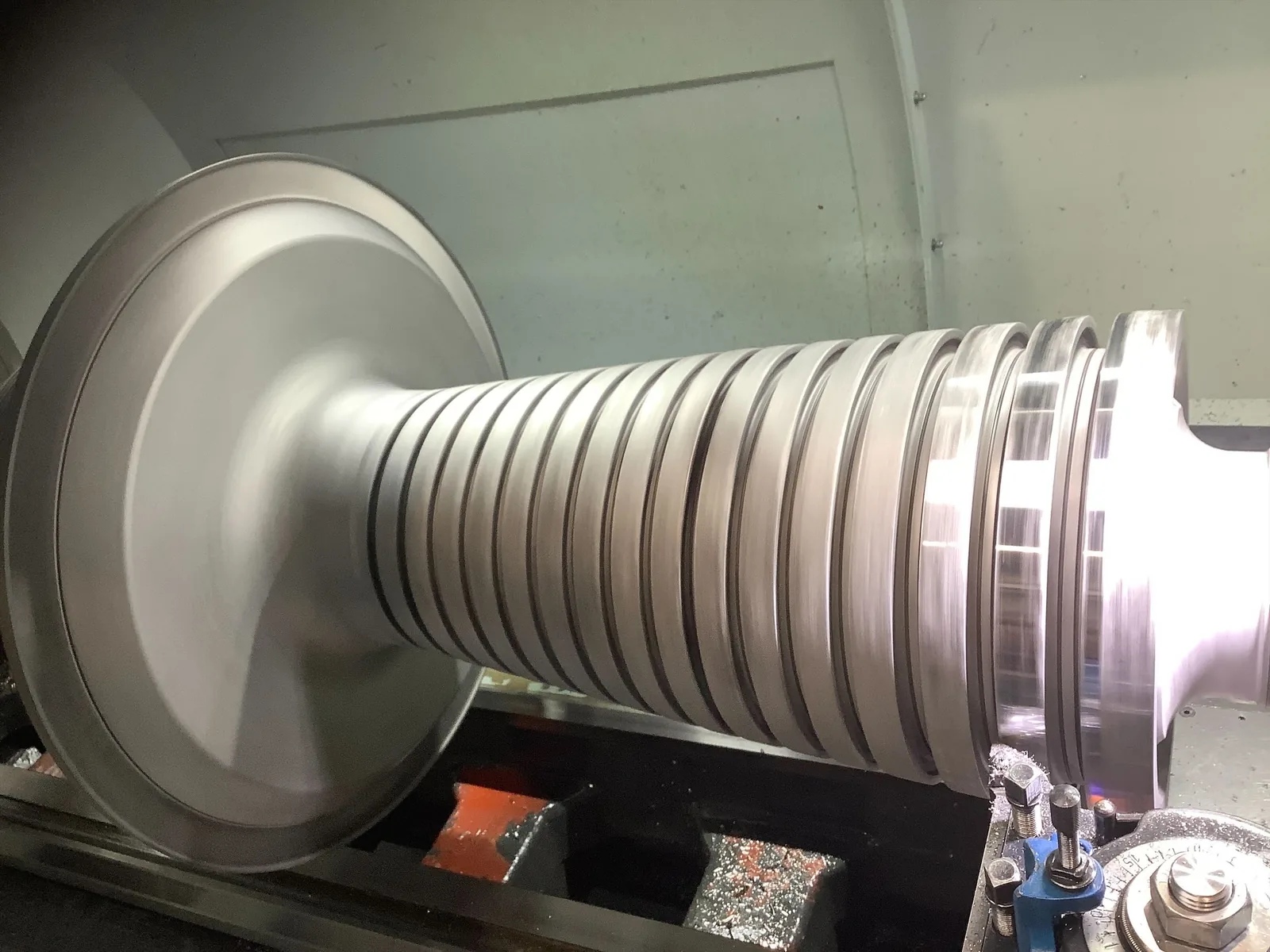
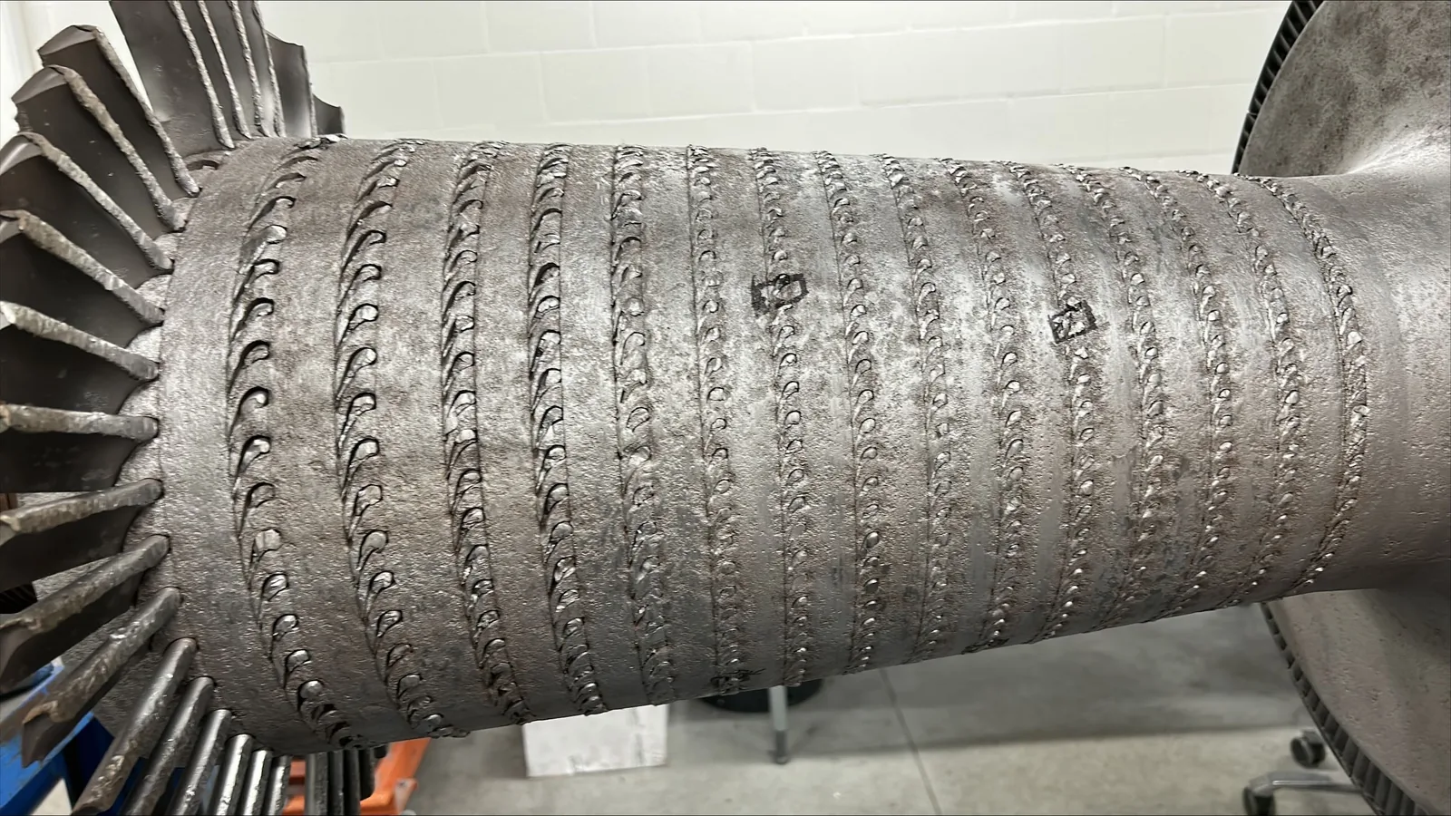
Rotor and stator were cleaned by glass pearl blasting. Non destructive testing followed on the blade grooves, using magnetic particle inspection and fluorescent penetrant inspection, to look for cracks and to decide which grooves could be reused as they were.
The straightness of the rotor was checked, with a maximum runout of 0.02 mm. That figure decided the direction of the whole project. A rotor that had bent under the event would have been a replacement discussion. A rotor that had stayed straight through a full circumferential rub was a rotor worth rebuilding.
Damaged areas and grooves were then machined to restore the dimensions the new blading needed.
New Blading, and a Better Blade Than the One That Failed
Manufacturing
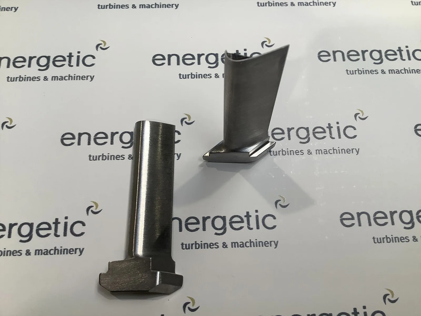
The complete set, rotor and stator, was manufactured new, delivered with dimensional and material certificates. Once installed, the blade tips were machined to the nominal operating clearances of the machine.
A Design Change That Was Worth Making
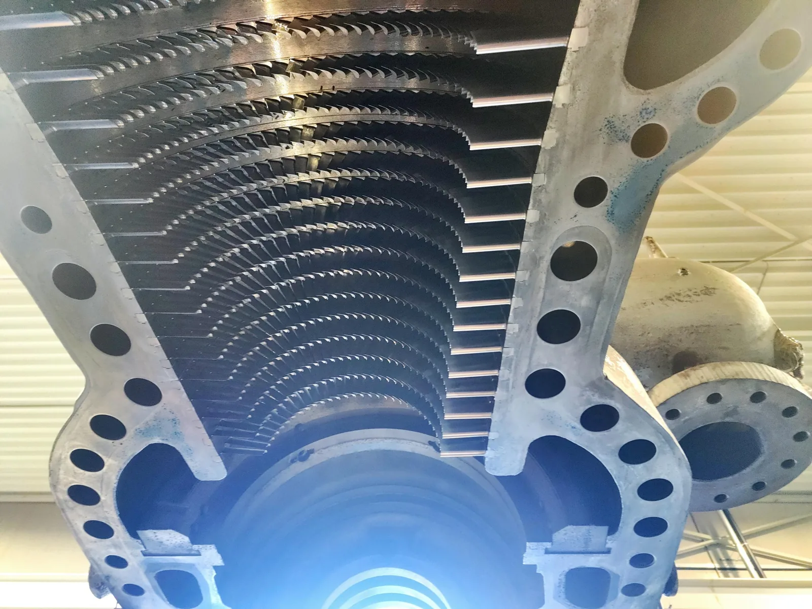
The original blading used a separate blade and root. The replacement was designed as a single solid piece, which removes the joint between blade and root and carries the higher loads that come with the machine's current operating conditions and lower outlet pressure.
This is the part of a reblading project that is easy to skip. Copying the original geometry is faster and nobody can criticise it. Re-engineering the blade for the duty the machine actually runs today costs engineering hours, and it is the reason the new blading is not simply a replacement of what failed.
Finally the rotor was high speed balanced, which is the validation step before a rotor goes back into a casing.
Everything Around the Steam Path
Seals and Casing
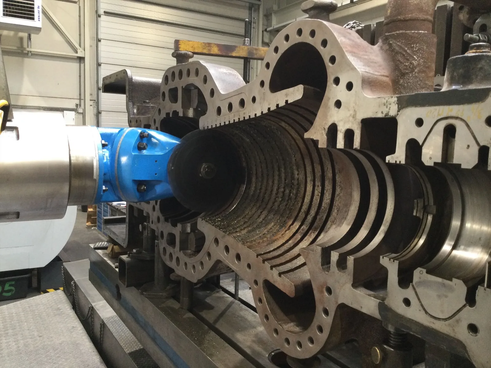
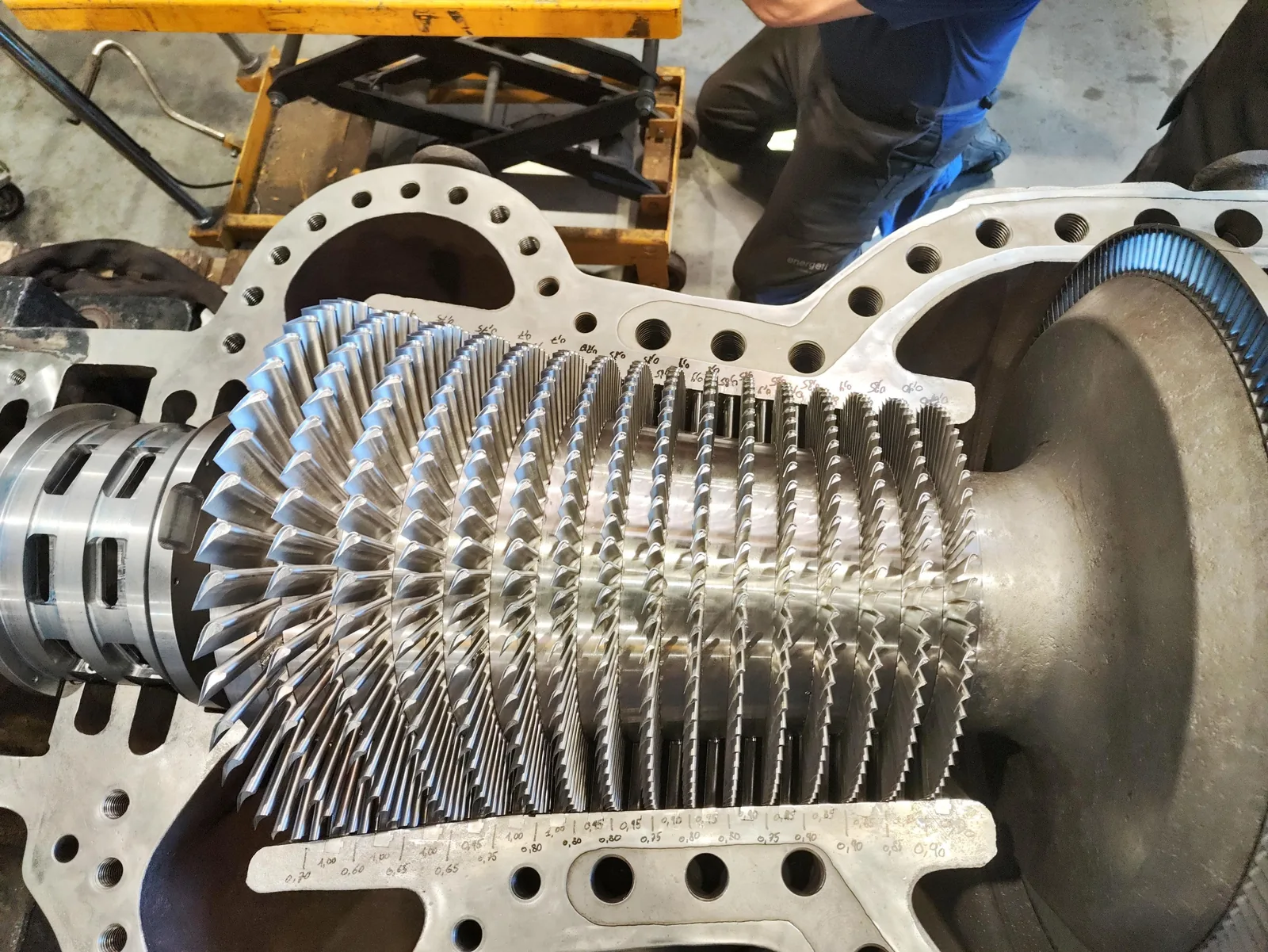
The intervention did not stop at the blading. Stuffing boxes, labyrinth segments and sealing strips were reverse engineered and manufactured new, and the new sealing strips were installed and machined in place.
The balance piston sealing system was renewed as well. Its condition would have allowed internal steam leakage, which shows up as lost output rather than as a fault, and is therefore the kind of thing that stays in a machine for years.
On the casing, new split line bolts and nuts were reverse engineered and manufactured, damaged threads in the casing were refurbished, steam discharge flanges were machined, and studs that had seized were removed by machining rather than by force.
Bearings and Control
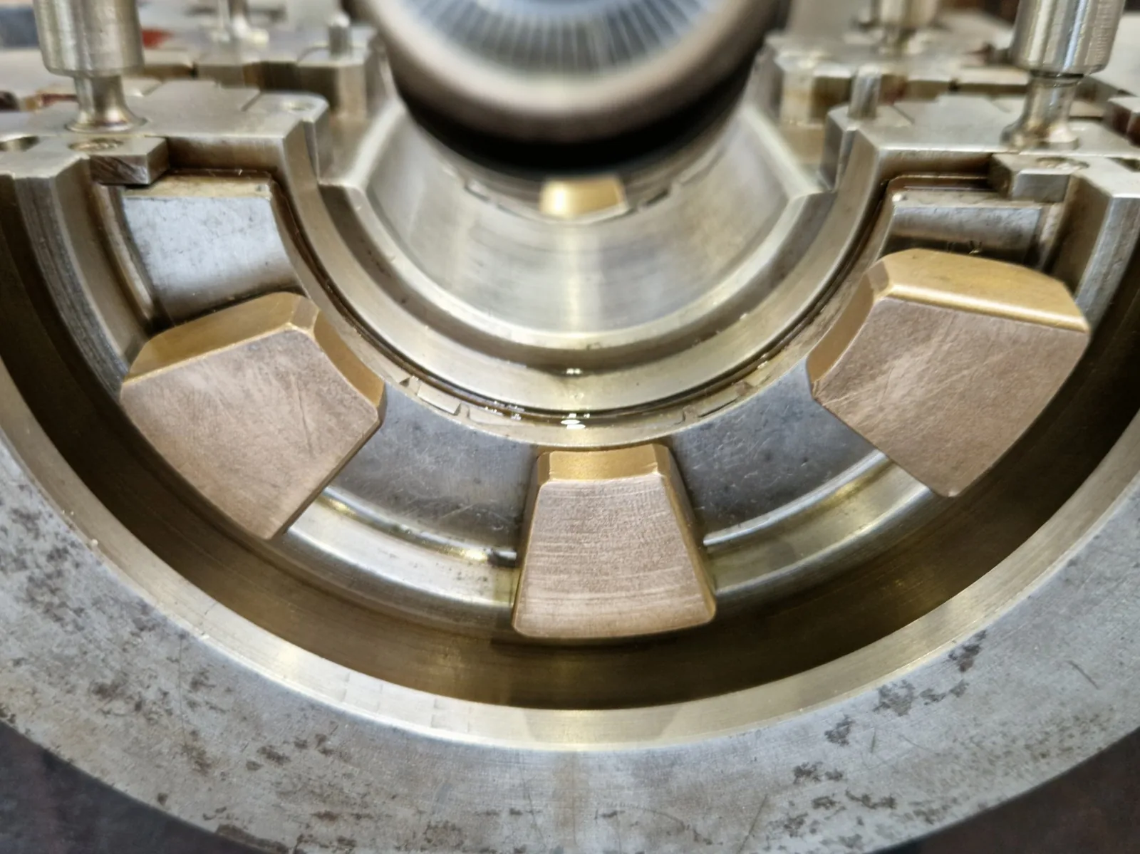
The turbine bearings on the drive end and the non drive end were repaired, and so were the pinion bearings on both sides. The actuators were overhauled, and the actuators and the hydraulic control system were tested and calibrated.
Preventing the Same Failure Twice
What the Damage Pattern Showed
During the inspection the most severe rubbing was found at the lower part of the balance piston seal carrier. That is consistent with the failure mechanism: the bottom of the machine is where water collects and where the temperature difference between top and bottom is largest.
Measuring the Thing That Actually Caused the Failure
The plant had no way of seeing the condition that destroyed the blading. Nothing in the control system measured the temperature difference across the machine during a start.
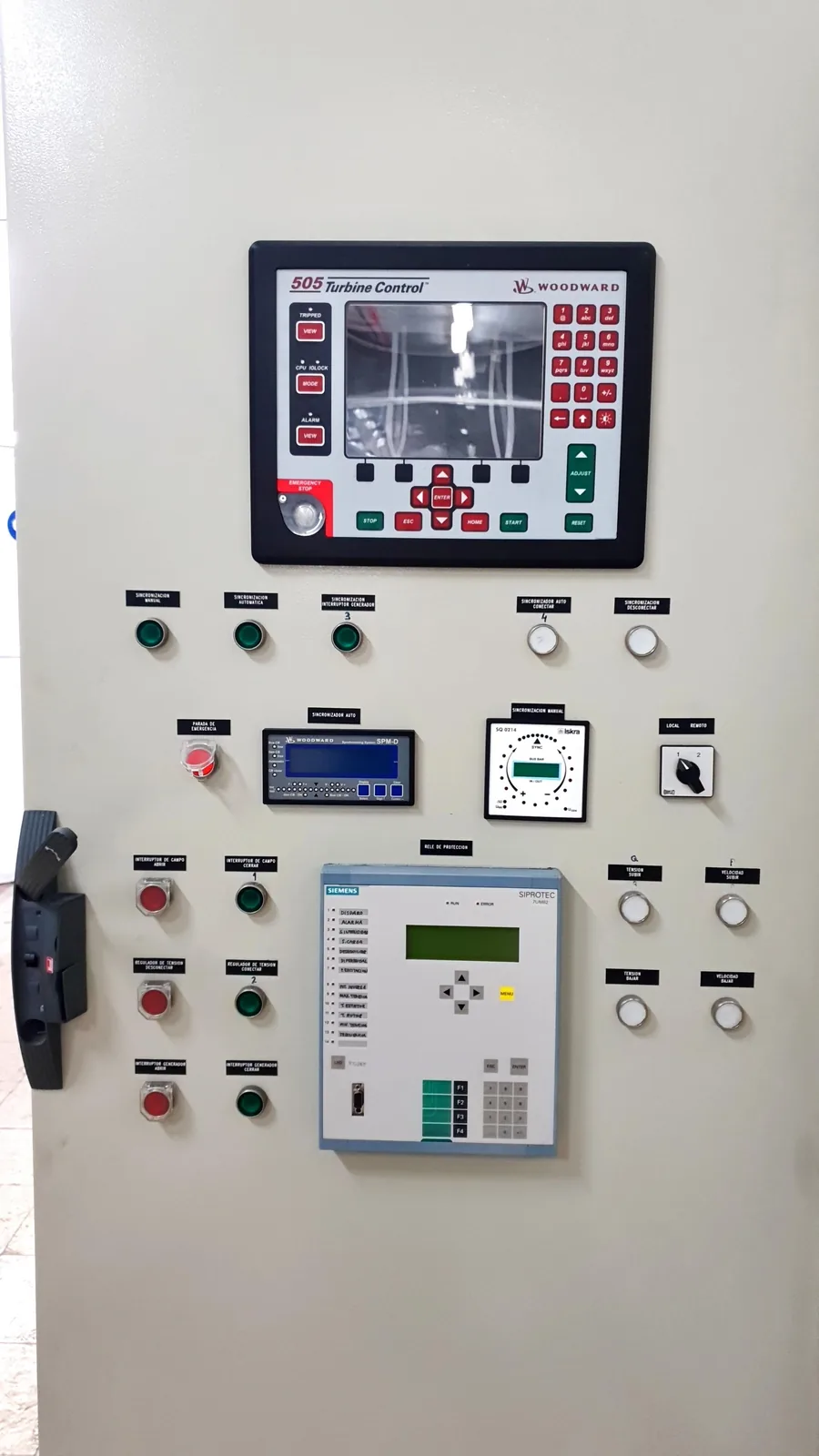
Energetic Machinery proposed thermocouples at the upper and the lower part of the seal carrier, so that the temperature difference between top and bottom is measured during warm up and start. The signal makes a thermal imbalance visible before it can close the clearances, and it can be used to permit or block a start rather than only to record what happened.
The control system was subsequently replaced by a Woodward system, which can use those temperature signals to determine whether the machine is in a condition for a cold start or a hot start.
This is the difference between repairing a failure and removing it. The blading was rebuilt in any case. The measurement is what makes the next unplanned stop survivable.
Start Up and Verification
After reassembly the turbine was started according to the normal procedure, with the oil system, the governor, the control valves and the machine protection checked during run up. The overspeed test was completed successfully, with the machine tripping at 8,523 rpm.
Vibration was measured on turbine, gearbox and generator. Turbine vibration stayed below 1 mm/s against a limit of 4.5 mm/s for long term operation. For a machine group 1 on a rigid foundation the measured levels are classified as new machine condition.
That classification is the point of the exercise. A rotor that had lost its entire blading, rebuilt with blades that did not exist as spare parts, came back into service running as well as a new machine.
Results
-
The rotor was recovered rather than replaced, on a measured runout of 0.02 mm.
-
Complete new blading over sixteen rows, 1,001 rotor blades and a full set of stator blades, engineered from the machine because no undamaged reference blade survived.
-
Blading redesigned as a single solid piece for the machine's current duty.
-
Stuffing boxes, labyrinth segments, sealing strips, balance piston seals and split line bolting reverse engineered and manufactured.
-
Overspeed trip verified at 8,523 rpm.
-
Turbine vibration below 1 mm/s against a 4.5 mm/s long term limit, classified as new machine condition.
-
Thermal monitoring added at the seal carrier, so that the condition that caused the failure is measured instead of assumed.
-
The result led to inspection of the other turbines on the site, and to blade replacement on further units.
FAQ: Blade Failure After a Restart
How can a short stop destroy a complete set of rotor blades?
Because the damage is not caused by the stop but by what happens during the restart. Water that has collected while the machine stood still can enter the steam path when it is put back in service. The rotor then cools and contracts faster than the casing, tip clearance goes to zero, and the blades touch across the whole rotor at once instead of one row at a time.
Why were the stator blades much less damaged than the rotor blades?
Because the rotating parts are the ones with energy. In a rub between a spinning rotor and a stationary casing, the rotor blades take the load and shear. Stator damage is consequential. That asymmetry is one of the indications that the event was a thermal rub rather than a foreign object or a mechanical failure.
Can a rotor that has rubbed over its whole length still be reused?
Often yes, and it is worth measuring before assuming otherwise. Here the maximum runout was 0.02 mm, so the rotor body had survived the event intact and only the blading and the grooves needed work. That measurement is what keeps a reblading project from becoming a rotor replacement project.
Why manufacture blades instead of ordering them?
Because there was nothing left to order against. Almost every one of the 1,001 rotor blades was destroyed and none could be recovered as a reference. The geometry of all sixteen rows had to be re-established by engineering from the machine and the documentation, which also created the opportunity to improve the blade root design instead of reproducing it.
What does a single solid piece blade change?
It removes the joint between blade and root. On a machine that now runs at a lower outlet pressure than it was originally designed for, the blading carries higher loads, and the joint is where a two part blade is weakest.
What stops this from happening again?
Measurement. Thermocouples at the top and the bottom of the seal carrier make the temperature difference across the machine visible during warm up, and that signal can be used to allow or block a start. Without it, a start after an unplanned stop is a judgement call with no data behind it.
Conclusion: The Diagnosis Decides the Repair
This case may be relevant if a machine has rubbed after a restart, if a turbine has been stopped and restarted at short notice without a controlled warm up, if the blading of an older machine can no longer be ordered from the original supplier, or if nothing in the control system measures the thermal condition of the machine before a start is permitted.
The turbine in this case was not worn out. It was destroyed in a few seconds by a condition that nobody could see. Rebuilding the steam path was the visible part of the work. Establishing why the clearances closed, and then measuring that condition permanently, is what made the repair worth more than the parts in it.
Energetic Machinery combines root cause investigation, reverse engineering, in house manufacturing of blading, seals and non standard components, and field service with commissioning support. That combination is what allows a machine with no surviving reference part to come back in new machine condition.